Mechanical Drawing Symbols【Dimension & Geometric Tolerance Symbols Explained】
A mechanical drawing is a "language of symbols." Dimension auxiliary symbols convey shape quickly, while geometric tolerance symbols rigorously specify allowances of form, orientation and location. Read the symbols correctly and a single drawing tells you the key points for machining and inspection. This guide covers dimension symbols, geometric tolerance symbols, datums and how to read the feature control frame — with a diagram.
Dimension auxiliary symbols (table)
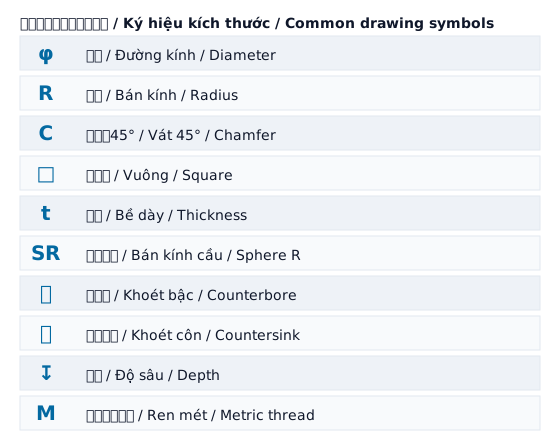
Fig. 1 — Common dimension symbols. Placed before/after a number to convey shape and meaning concisely.
φ(phi) = diameter,R= radius,SR= sphere radius.C= 45° chamfer (e.g.,C2),□= side of a square,t= plate thickness (e.g.,t3.2).⌴= counterbore,⌵= countersink,↧= depth (e.g.,⌀8 ↧10).M= metric thread (e.g.,M8).
Geometric tolerance symbols
Specify allowances of "form · orientation · location · runout" that dimensions alone can't express.
| Category | Example symbols | Meaning |
|---|---|---|
| Form | straightness, flatness, roundness, cylindricity | Form error of a single feature |
| Profile | line profile, surface profile | Error of a curve/profile |
| Orientation | parallelism, perpendicularity, angularity | Orientation relative to a datum |
| Location | position, concentricity, symmetry | Location relative to a datum |
| Runout | circular runout, total runout | Runout when rotated |
Unstated form errors fall under general geometric tolerances (JIS B 0419).
Datums (references)
The face/axis/point that serves as the "reference" for a geometric tolerance is a datum, marked A·B·C. Orientation/location/runout tolerances must always be read together with the datum they reference.
Reading the feature control frame
Read the frame left to right: "symbol | tolerance value | datum."
Example: ⟂ | 0.02 | A → "perpendicularity within 0.02mm relative to datum A."
It may carry a maximum material condition (Ⓜ) or datum precedence, e.g., ⌖ | φ0.1 Ⓜ | A B C.
The surface texture symbol
Roughness is specified with its own symbol (a check mark), carrying an Ra value like Ra 1.6, plus machining method and lay direction. See the surface roughness article.
Common mistakes
- Confusing
φandR(diameter vs. radius). - Reading a geometric tolerance without its datum (orientation/location/runout require one).
- Mixing up a
Cchamfer and anRcorner radius. - Reading the frame order backwards (symbol → tolerance → datum).
Frequently asked questions (FAQ)
Q. Are φ and ⌀ the same? A. Both mean diameter; only the glyph differs.
Q. Does a geometric tolerance always need a datum? A. Form tolerances (straightness, flatness...) don't, but orientation/location/runout do.
Q. What is Ⓜ (M in a circle)? A. Maximum material condition (MMC) — it allows bonus tolerance when the part is at its maximum material size.
Q. Chamfer C vs. R?
A. C is a straight 45° chamfer; R is a rounded corner (arc).
Q. What about unstated form accuracy? A. General geometric tolerances apply (JIS B 0419, grades H/K/L).
Summary
Drawing symbols are a language: "dimension symbols describe shape, geometric tolerance symbols describe allowance." Read the frame as "symbol → tolerance value → datum" and understand it together with the datum. Read the symbols and the machining and inspection priorities become obvious at a glance.
Sontis Management keeps drawings, machining conditions and inspection standards together with materials, quotes and orders. Try it on the free plan.
Manage quotes & inventory — free, starting today.
No credit card · 5 minutes to start. Management software for machine shops.
Start for free