How to Read a Three-View Drawing【Third-Angle Front/Top/Side Views Explained】
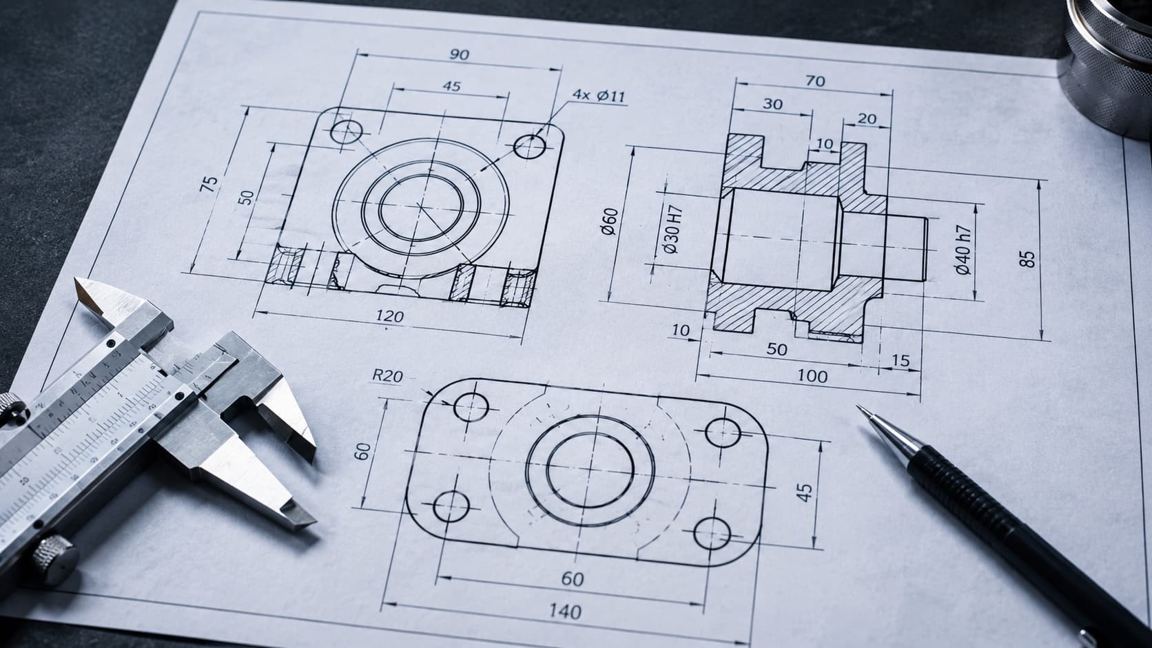
A three-view drawing represents a 3D object from three directions — front, top and side — and is the basic form of a mechanical drawing. The three views are linked by "projection relationships," and once you know the layout rules you can rebuild the solid in your head. This guide covers third- vs. first-angle projection, the layout, line types and a reading procedure — with a diagram.
What a three-view drawing is
- Front view: the base view, seen from the direction that shows the shape best.
- Top view: seen from above.
- Side view: seen from the side (usually the right).
- The three views align vertically and horizontally, and the same dimension matches across views.
Third-angle vs. first-angle projection
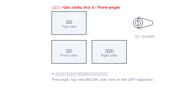
Fig. 1 — Third-angle layout. In third-angle projection (common in Japan and North America), with the front view at the center, the top view goes above and the right-side view goes to the right (a layout intuitive to the viewing direction). First-angle projection (used in Europe, etc.) reverses top–bottom and left–right. The drawing carries a symbol indicating the projection, so check it first.
Layout (third angle)
- The top view sits directly above the front view; the right-side view is to the right.
- Views correspond via projection lines: front–top match on the vertical, front–side match on the horizontal.
- Using the correspondence, you can infer the third view or the solid from two views.
Line types
| Line | Use |
|---|---|
| Thick solid | Visible outline (seen edges) |
| Dashed | Hidden line (unseen edges) |
| Thin chain (dash-dot) | Center line · reference line |
| Thin dash-double-dot | Phantom line (motion range, adjacent parts) |
| Thin solid | Dimension line · leader · hatching |
Steps to visualize the solid
- Check the projection method (third/first) by its symbol.
- Grasp the overall shape from the front view.
- Correspond via projection lines with the top/side views to add height and depth.
- Read internal holes and steps from the dashed lines.
- Confirm symmetry and circle centers from center lines.
Common pitfalls
- Reading a first-angle drawing as third-angle and interpreting top–bottom/left–right backwards.
- Mistaking hidden lines (dashed) for visible outlines.
- Judging from one view instead of using the three-view correspondence.
- Confusing a center line with a dimension line.
Frequently asked questions (FAQ)
Q. How do I tell third- from first-angle? A. By the drawing's symbol (a truncated-cone mark) and the title-block note.
Q. Why do I need three views? A. One or two views don't fix depth and hidden shape. Three directions make the solid unique.
Q. Left or right side view? A. Third-angle usually places the right-side view on the right. A left-side view can be drawn on the left when needed.
Q. What about a drawing full of dashed lines? A. It's a part with much internal shape; a section view (hatching) can make it clearer.
Q. Are there more than three views? A. Yes. Complex parts add section, detail and auxiliary views.
Summary
A three-view drawing arranges "front, top, side" by projection relationships. First confirm the projection method, then use the front view as your axis and correspond via projection lines to build the solid. Distinguish the line types (visible, hidden, center) and you can read even the internal shape accurately.
Sontis Management keeps drawings, machining conditions and inspection standards together with materials, quotes and orders. Try it on the free plan.
Manage quotes & inventory — free, starting today.
No credit card · 5 minutes to start. Management software for machine shops.
Start for free